J Navig Port Res > Volume 43(5); 2019 > Article
Lee, Lee, Kim, and Cho: Identification of Impact Factors in Ship-to-Ship Mooring Through Sensitivity Analysis

ABSTRACT

With the recent increase in the volume of liquid cargo transportation, there is a need for STS( Ship To Ship) globally. In the case of the STS mooring, the safety assessment should be conducted according to other criteria because mooring is different from the general mooring at the quay, but there is no separate standard in Korea. Thus in this study, STS mooring simulation and sensitivity analysis using OPTIMOOR program, the numerical analysis program, was conducted to identify the characteristics of the STS mooring. The target sea modeled the Yeosu port anchorage in Korea and the target ship was selected as the case of VLCC (Very Large Crude Oil Carrier)-VLCC. Through the numerical simulation and sensitivity analysis, the characteristics of STS mooring were identified. Also based on these results, we focused on establishing the standard for STS mooring safety assessment. Numerical simulation results show that the STS mooring safety can be changed according to a ship’s cargo loading condition, pre-tension of mooring line, sea depth, encounter angle with the weather, and the weather condition. Additionally, the risk matrix is prepared to establish the safe external force range in the corresponding sea area. This result can be used to understand the mooring characteristics of STS and contribute to the revision of mooring safety assessment criteria.

1. Introduction

Offshore STS (Ship-to-ship) Transfer is a direct cargo transfer from ship to ship at an offshore STS terminal. It is mainly used for crude oil carriers such as VLCC (Very Large Crude-oil Carrier), which is difficult to berth at the pier because of draft restrictions in port. There is no need for a dredging depth in the port, and there are no limitations of the existing method that can be transfer only in limited docks. In addition, cargo operation is possible at no additional cost. if the anchorage space is enough to work without limiting berths. These advantages have resulted in the continued expansion of STS terminals worldwide (OCIMF, 2013).
Conventional STS operation has been used for transfer of liquid cargo such as oil, but STS operation is now applied to liquefied gases such as LPG (Liquified Petroleum Gas) and LNG (Liquified Natural Gas) and bulk cargo such as iron ore (Dimitrios and Nikolaos, 2014).
However, in spite of these advantages, there is a high risk because the STS terminal is located in the open sea due to its characteristics. And there is a high risk of mooring between ships and ships that are not mooring onshore port facilities. In particular, most STS vessels are mainly oil carriers, so safety measures are essential as they can lead to large oil spill accidents.
Since STS transfer is more difficult and more dangerous than ordinary mooring operations, it is essential to check safety precautions and check various equipments in accordance with OCIMF's recommendations and relevant port enforcement regulations (OCIMF, 2013; Witkowska et al., 2017).
To reduce the risk of such STS operation, Dimitrios and Nikolaos(2014) sought to reduce the risk of STS accidents through risk assessment by applying the FIS (Fuzzy Inference System) to STS work.
Dimitrios and Nikolaos(2016) proposed a new approach applying Process Failure Mode and Effect Analysis (PFMEA) to effectively assess the risks of STS work.
Yoo et al.(2014) developed the Velocity Information GPS (VI-GPS) to accurately check the relative speed and distance between ships in STS operation, improving the safety and efficiency of STS operations.
Sakakibara and Yamada(2008) have experimented with the method of selecting the fender according to the berthing energy of the ship during the STS operation and proposed the results as a recommendation to the OCIMF (Oil Companines International Marine Forum).
In general, STS transfer can be divided into three types(Double banking, Underway STS, Offshore STS). Double banking is a form where the mother ship is berthed at the pier and the daughter ship is mooring directly to the mother ship. Underway STS means that two vessels are moored to carry out cargo handling operations during navigation. Lastly, offshore STS refers to the type in which the mother ship is anchoring and the daughter ship is mooring to the mother ship.
In this study, mooring safety assessment simulation of offshore STS between 325,000 DWT(Deadweight) class VLCCs was conducted by modeling the anchorage of Yeosu port in Korea. The characteristics of the STS moorings were confirmed through sensitivity analysis of various mooring impact factors such as ship loading condition, pre-tension of mooring lines, sea depth and encounter angle with weather. Also, the risk matrix with different external force conditions was drawn up to set the safety external force range in the sea area.

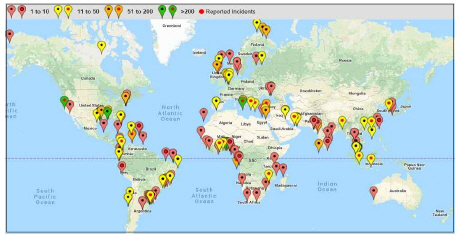
2. The status of Ship-to-ship transfer

STS transfer is a significant part of the world's energy flow, and the location of the STS terminal in the world is shown in Fig. 1 (Nikolaos and Dimitrios, 2013). As shown in Fig. 1, STS transfer is actively operated in more than 50 ports including Yeosu port in Korea.
Fig. 1
Place of STS transfer
KINPR-43-5-310_F1.jpg
In Fig. 2, statistics on the types of accidents that occurred during STS operation, it can be seen that mooring line-related accidents accounted for the highest rate of 73%. In addition, the damage of the fender accounted for about 11% after the mooring line accident, indicating that mooring safety-related accidents accounted for a high percentage of the total accidents. Therefore, it is important to conduct an accurate mooring safety assessment before STS operation.
Fig. 2
Type of accident during STS transfer
KINPR-43-5-310_F2.jpg

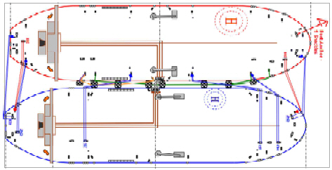
3. Mooring safety assessment of STS

3.1 Summary of mooring safety assessment
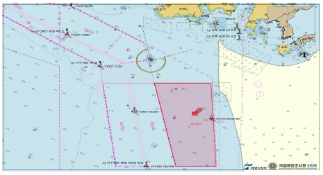
In general, the mooring safety assessment of ships is performed by analyzing the loads of mooring systems such as mooring lines, fenders, and bollards under the natural external force conditions of the target sea area.
In this study, the mooring safety assessment for STS cases was performed by dynamic analysis using the latest version of OPTI-MOOR SW (Ver.6.2.6) of TTI (Tension Technology International). This software is simpler to use than other mooring safety analysis programs. However, this program is an analysis program that is representatively used when performing mooring safety assessment of maritime traffic safety diagnosis in Korea because it can be accurately modeled (Kim et al., 2016; Cho, 2017; Lee and Kim, 2019).

(1) Target sea area

In this study, the anchorage in Yeosu, Korea was selected as the target sea area for the numerical simulation of the STS mooring safety assessment. In Yeosu port, which is the target sea area, the VLCCs have frequent entry and exit ports, and the amount of crude oil processed in the port has been confirmed (Jong et al., 2005; Kim et al., 2006). The chart of the port is shown in Fig. 3.
Fig. 3
Location of the target sea area (Yeosu anchorage)
KINPR-43-5-310_F3.jpg

(2) Target vessel

The target vessel for mooring safety assessment was selected as the VLCC of 325,000 DWT class among the ships carrying out the STS operation, and the main specifications of the vessel are shown in Table 1.
Table 1
Main specification of 325,000 DWT class VLCC
KINPR-43-5-310_T1.jpg
Mooring lines, fenders and anchor connecting between the vessels are set as shown in Table 2. The mooring line was modeled as a 42mm wire rope mooring line that was frequently used in VLCCs. The fenders adopted 3,300 D(Diameter) x 6,500 L(Length) pneumatic fenders that were easy to install during STS transfer.
Table 2
Specification of mooring line, fender and anchor
KINPR-43-5-310_T2.jpg
The arrangement of mooring lines was modeled in OPTIMOOR with reference to Fig. 4, which is an actual mooring arrangement used in the field.
Fig. 4
Mooring configuration (VLCC-VLCC)
KINPR-43-5-310_F4.jpg

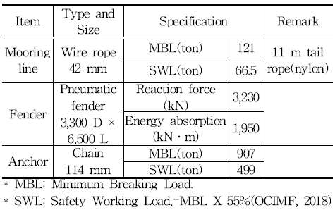
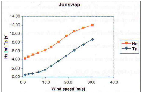
(3) Natural external condition

The external force conditions applied in the mooring safety assessment in this study were evaluated by applying the maximum external force or adverse external force based on the Yeosu Port guidelines for offshore STS transfer as shown in Table 3.
Table 3
Weather condition by guidelines of offshore STS transfer in Yeosu port
KINPR-43-5-310_T3.jpg
The OPTI-MOOR program performs a series of calculations to satisfy the force and moment equations for mooring lines. This equation is referred to the program guide and can be expressed as Eqs. (1)-(3) (Ractliffe and Flory, 2012).
(1)
Fx+Px=0
(2)
Fy+Py=0
(3)
Mxy+Nxy=0
Where:
  • Fx : the x vector component of an externally applied force, (e.g. wind, current)

  • Px : the x vector component of a mooring line force (fenders exert no force in the x direction).

  • Fy : the y vector component of an externally applied force, (e.g. wind, current)

  • Py : the y vector component of a mooring line force (fenders exert no force in the x direction).

  • Mxy : the moment in the x-y plane produced by an externally applied force, (e.g. wind, current)

  • Nxy : the moment in the x-y plane produced by a mooring line force or fender force.

The wind force required for the mooring line force and moment equations is defined as the component of the vertical force at the ship's centerline, which is based on the Optimoor guidelines and can be expressed as Eq. (4) (Ractliffe and Flory, 2012).
(4)
(FXFYMZ)=12ρairVWIND2A(CXCYLPPCN)
Where:
  • FX : Longitudinal force due to wind (Surge)

  • FY : Lateral force due to wind (Sway)

  • MZ : Yawing moment due to wind

  • LPP : Length between perpendiculars

  • CX, CY, CN : Wind force coefficient (Surge, sway, yaw)

The current force required for the mooring line force and moment equations is defined as the component of the vertical force at the ship's centerline, which can be expressed as Eqs. (5)-(7) (Ractliffe and Flory, 2012).
(5)
FXc=12CXcρwVC2LPPT
(6)
FYc=12CYcρwVC2LPPT
(7)
MZc=12CZcρwVC2LPPT
Where:
  • FXc : Longitudinal force due to current (Surge)

  • FXc : Lateral force due to current (Sway)

  • MZc : Yawing moment due to current

  • CXc, CYc, CZc : Current force coefficient

  • ρw : Density of sea water

  • VC : Velocity of current

  • Lpp, T : Length between perpendiculars, draft of vessel

3.2 Sensitivity analysis

In this study, sensitivity analysis was performed to identify the characteristics of STS mooring. Factors influencing the sensitivity analysis were selected as the ship’s loading condition, pre-tension of the mooring line, sea depth and the encounter angle with the external force. Scenarios for sensitivity analysis were prepared and evaluated as shown in Table 4.
Table 4
Scenario for sensitivity analysis
KINPR-43-5-310_T4.jpg

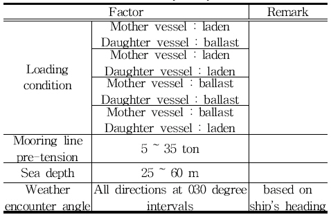
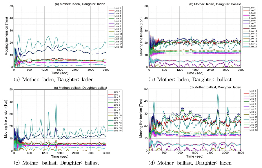
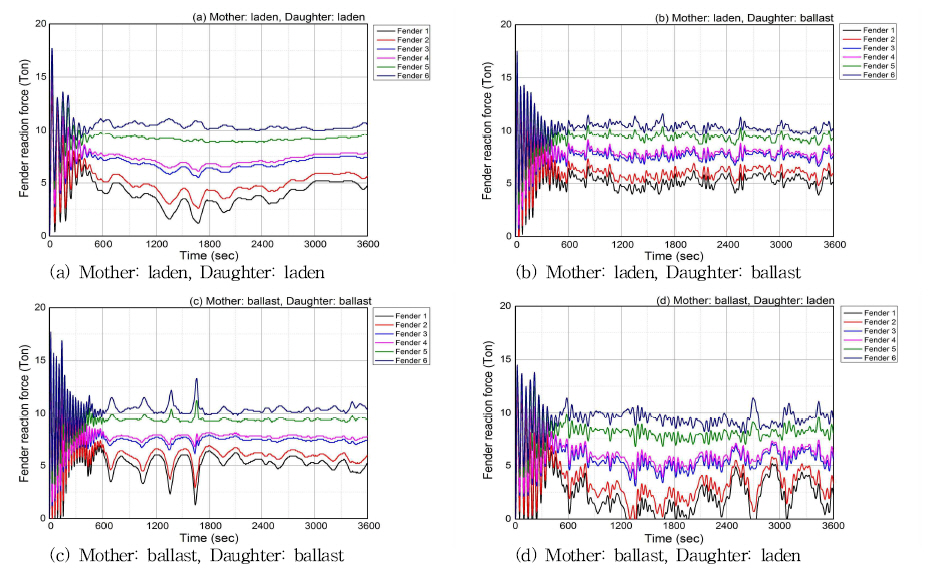
(1) Ship’s loading condition

In the sensitivity analysis according to the ship's loading conditions, the following four types were analyzed according to the state of mother ship and daughter ship.
  1. Mother ship: Laden, daughter ship: Laden

  2. Mother ship: Laden, daughter ship: Ballast

  3. Mother ship: Ballast, daughter ship: Ballast

  4. Mother ship: Ballast, daughter ship: Laden

Fig. 5 shows the time series analysis of the tension of the mooring line for each case.
Fig. 5
Time series of the mooring line tension by loading condition
KINPR-43-5-310_F5.jpg
As shown in Fig. 5, when the mother ship is in full loaded, the maximum tension of mooring line is smaller than when the mother ship is in ballast condition. However, it can be seen that the maximum tension of mooring line according to the condition of the daughter ship does not change significantly.
In mooring safety of STS, not only the tension change of mooring line but also the reaction force of fender is important in mooring safety part. Fig. 6 shows the time series analysis of the reaction force change of the pneumatic fender located between the ships.
Fig. 6
Time series of the fender reaction force by loading condition
KINPR-43-5-310_F6.jpg
As a result of analyzing the reaction force of the fenders in time series, it can be seen that the change of the reaction force with time is different in the state of the mother ship and the daughter ship, but in the case of maximum reaction of fender, it is confirmed that there is no big difference by about 15 ~ 17 tons according to each case.
Fig. 7 shows the results of comparing the maximum tension applied to mooring lines and the maximum reaction force applied to the fender according to the ship's loading condition. The reason why M:L-D:B is different from M:B-D:L appears to be due to the anchoring in port side of the mother ship. The maximum tension of the mooring line was measured the smallest when both the mother ship and the daughter ship were laden condition, and the largest when the mother ship was in ballast condition and the daughter ship was laden condition. In addition, when the mother ship is in laden condition, the tension of mooring line is smaller than when the mother ship is in ballast condition.
Fig. 7
Comparison for Maximum force of mooring line and fender depending on loading condition
* M : Mother ship, D : Daughter ship
* L : Laden condition, B : Ballast condition
KINPR-43-5-310_F7.jpg

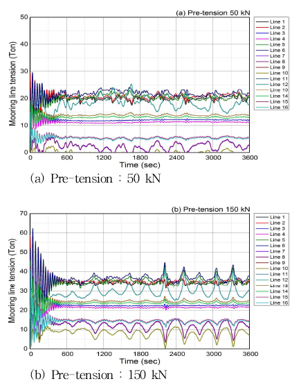
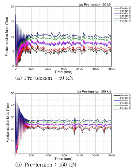
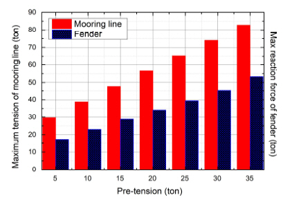
(2) Mooring line pretension
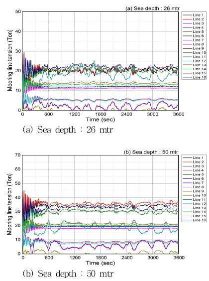
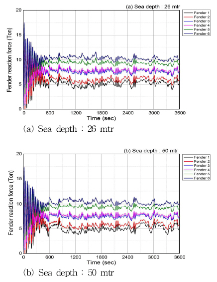
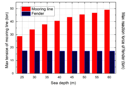
In the sensitivity analysis according to the pre-tension of mooring line, the tension of mooring lines and the reaction force of fenders were analyzed when the pre-tension was 50 kN and 150 kN. Fig. 8-9 are the time series analysis of the change of mooring line tension and the fender reaction force according to the pre-tension changed.
Fig. 8
Time series of the mooring line tension by pre-tension
KINPR-43-5-310_F8.jpg
Fig. 9
Time series of the fender reaction force by pre-tension
KINPR-43-5-310_F9.jpg
As shown in Fig. 8, the maximum tension of the mooring line was about 30 tons when the pre-tension is 50 kN. However, when the pre-tension is increased to 150 kN, the maximum tension of the mooring line is 65 tons, which can be increased more than twice as much.
The fender reaction force also increased significantly according to the pre-tension as shown in Fig. 9.
Fig. 10 shows the results of comparing the maximum tension applied to the mooring line and the maximum reaction force acting on the fender according to the change of the pre-tension of the mooring line. In the mooring line and the fender, it can be seen that the maximum tension and the maximum reaction force increase as the pre-tension increases.
Fig. 10
Comparison for Maximum force of mooring line and fender depending on pre-tension
KINPR-43-5-310_F10.jpg

(3) Sea depth

In the sensitivity analysis according to the depth change, we tried to find out the difference between the depth of 26 mtr in Yeosu port and 50 mtr depth in other seas. Fig. 11-12 are the time series analysis for the change of mooring line tension and fender reaction force according to the sea depth change.
Fig. 11
Time series of the mooring line tension by sea depth
KINPR-43-5-310_F11.jpg
Fig. 12
Time series of the fender reaction force by sea depth
KINPR-43-5-310_F12.jpg
The time series of mooring line tension according to the sea depth change in Fig. 11 shows that the maximum tension of the mooring line is about 30 tons at 26 mtr of sea depth, but the maximum tension increases to about 45 tons as the sea depth deepens to 50 mtr.
However, as shown in Fig. 12, the time series of fender reaction force, it can be seen that the reaction force change of fender is relatively unaffected by sea depth.
Fig. 13 shows the results of comparing the maximum tension applied to mooring lines and the maximum reaction force applied to the fender according to the change of sea depth. In the case of the maximum mooring line tension, the trend increased as the depth increased. But the maximum reaction force of the fender can be confirmed that there is no significant change. The reason for this difference is considered due to the hull movement caused by the complex factors such as the mother ship's anchor and the UKC (Under Keel Clearance).
Fig. 13
Comparison for Maximum force of mooring line and fender depending on sea depth
KINPR-43-5-310_F13.jpg

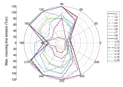
(4) Encounter angle with weather

In the sensitivity analysis according to the change of the encounter angle with the external force, the direction of the external force acting on the hull was evaluated as 360 degrees by dividing the direction by 030 degrees based on the bow direction (000 degree).
Fig. 14-15 shows the results of the graph comparing the maximum tension of mooring line and maximum reaction force of fender according to the encounter angle with external force.
Fig. 14
Maximum mooring line tension based on encounter angle
KINPR-43-5-310_F14.jpg
Fig. 15
Maximum fender reaction force based on encounter angle
KINPR-43-5-310_F15.jpg
In the case of maximum tension of mooring lines, the maximum tension increases greatly as the encounter angle with the external force when the hull is closer to the lateral direction (090 degree, 270 degree). However, it can be seen that the maximum tension decreases as the encounter angle with the external force approaches the bow direction (000 degree) or the stern direction (180 degree).
In the case of fender, unlike the mooring line, the largest maximum reaction force occurs in the starboard stern direction (240 degree) and the stern direction (180 degree).

4. Risk matrix based on weather condition

In this study, in addition to the sensitivity analysis, the risk matrix was prepared according to the external force change to derive the weather condition of wind and wave which is dangerous for the STS transfer in the target sea area.
The wave condition was set by varying the wave significant height (1.0-3.0m) and wave period (6-14sec). Wind speed was determined using Modified Jonswap graph as shown in Fig. 16. The value of current force was fixed by adopting the maximum current in the target sea area.
Fig. 16
Modified Jonswap graph
* Hs : Significant wave height, m
* Tp : Wave period, sec
Source : OCIMF, 2013
KINPR-43-5-310_F16.jpg
In preparing the risk matrix, the classifications of “Safety”, “Caution” and “Danger” were evaluated according to the criteria shown in Table 5.
Table 5
Evaluation standard for risk matrix
KINPR-43-5-310_T5.jpg
In other words, the criterion for “Safety” is that the maximum mooring line tension is within 40% of breaking strength, and the maximum reaction force of fender is within 80% of breaking load. In case of “Caution”, the maximum mooring line tension was set within 45 ~ 55% of breaking strength, or the maximum reaction force of fender was within 80 ~ 100% of breaking load. In the case of “Danger”, the risk was determined when the maximum mooring line tension exceeded 55% or when the maximum reaction force of the fender exceeded 100% of the breaking load.
Based on these criteria, the risk matrix according to external force changes is shown in Fig. 17.
Fig. 17
Risk matrix depending on external force at Yeosu port
KINPR-43-5-310_F17.jpg
As shown in Fig. 17, the mooring safety was not satisfied at the wave period of 12 seconds and was evaluated as "Danger". In the case of the wave period of 10 seconds, mooring safety level was evaluated as "Danger" up to wave significant height 2.0m, and at wave significant height 1.5m it can be seen that it is evaluated as "Caution".
Such a risk matrix preparation can identify safety external conditions in advance for STS operations in the target sea area, so that it is possible to determine the possibility of work and urgent issues as the external conditions deteriorate and contribute to the prevention of safety accidents.

5. Conclusion

STS transfer has a merit that enables the cargo operation with large ships such as VLCCs which are difficult to enter into the port because there is no depth limit. Therefore, the construction of STS terminals is increasing worldwide. However, there is a risk that large-scale oil spill accidents may occur during offshore transfer and more dangerous than cargo operation in berth, so studies for mooring safety precautions and safety assessment in STS cases are essential.
In this study, sensitivity analysis of ship's loading condition, pre-tension of mooring line, sea depth and encounter angle with external force was conducted to understand the characteristics of these moorings. In addition, a risk matrix was developed to derive safe external forces for STS mooring in the target sea area.
Through the sensitivity analysis of various factors, we tried to identify factors that affect STS mooring and characteristics of mooring. By creating a risk matrix, we tried to identify the limit conditions of natural external force conditions in STS operation and to prevent safety accidents during cargo work. The results are summarized below.
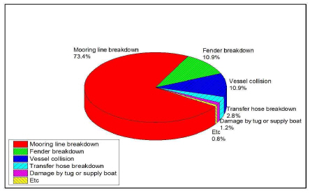
  • (1) During the STS mooring, sensitivity analysis was performed according to the change of the ship's cargo loading condition, pre-tension of the mooring line, the sea depth, and the encounter angle with the external force.

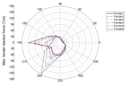
    As a result of analyzing the cargo loading of the mother ship and daughter ship separately from the laden and ballast condition, it was found that when the mother ship's loading condition was in laden condition, the maximum tension of the mooring line was increased. However, the maximum reaction force of the fender did not change significantly depending on the ship's loading condition.
    In the case of the mooring line's pre-tension, as the pre-tension increases, the force acting on both the mooring line and the fender increases. The result shows that the mooring line's pre-tension has a significant effect on the STS mooring. Considering this, it can be seen that the pre-tension of mooring line needs to be properly confirmed in the case of the STS mooring safety assessment.
    In case of sea depth, the maximum tension of mooring line increased with deepening sea depth, but it was confirmed that there was no significant effect on the maximum reaction force of the fender.
    As a result of confirming the encounter angle with the external force for 360 degrees in 30 degree intervals, the maximum tension of the mooring line acted stronger as it was closer to the transverse direction and a smaller tension in the lateral direction. In contrast to the mooring line, the maximum reaction force of the fender was confirmed that the strong reaction force acted in the starboard stern direction and the stern direction.
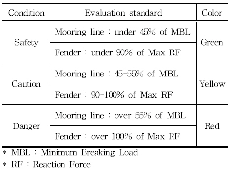
  • (2) The risk matrices for the STS moorings were evaluated in three stages: safety, caution and risk. In case of securing safety, it was evaluated as “Safety”(Green). If careful attention should be given to cargo operations, and if it is necessary to prepare for the immediate discontinuation of the operation, it may be classified as “Caution”(Yellow) and when safety is not secured and urgent response is required, it is classified as “Danger”(Red).

    Through the risk matrix, it was found that the STS operation conditions at Yeosu anchorage should be less than 10 seconds of wave period with less than 1.0m wave significant height or less than 8 seconds of wave period with less than 2.0m of wave significant height.
    In this study, a numerical analysis program was used to evaluate the differences in safety factors during STS mooring. Through this, STS mooring characteristics were confirmed by identifying factors affecting STS mooring safety. This not only enables the identification of the influence factors to be considered in setting the target area, but also can be used as a resource to check the factors to be careful during STS operation. In addition, it is expected to prevent damage due to bad weather in the port through measures for external force change during STS operation by identifying the limit external force condition in the relevant area by creating a risk matrix for mooring safety.

REFERENCES

1. Cho, I. S.(2017 “Behavior Analysis and Control of a Moored Training Ship in an Exclusive Wharf”, Journal of Korean Society of Marine Environment & Safety, Vol. 23, No. 2, pp. 139-145. .
2. Dimitrios, I. S. and Nikolaos, P. V.(2014 “Ship to Ship Transfer of Cargo Operations: Risk Assessment Applying a Fuzzy Inference System”, Journal of Risk Analysis and Crisis Response, Vol. 4, No. 4, pp. 214-227. .
3. Dimitrios, I. S. and Nikolaos, P. V.(2016 “A novel approach in risk evaluation for ship-to-ship (STS) transfer of cargo using process failure mode and effects analysis (PFMEA)”, Journal of Risk Research, Vol. 19, No. 7, pp. 913-933. .
4. Dynamarine2018), Ship-to-ship incident analysis in OSIS database, http://www.onlinests.net .
5. Jong, J. Y.,, Kim, C. S. and Jeong, J. S.(2005 “A Study on Proposal of the Improved Marine Traffic System for Specified Area on Yosu Bay”, Journal of Navigation and Port Research, Vol. 29, No. 8, pp. 653-660. .
6. Kim, C. S.,, Jong, J. Y. and Park, Y. S.(2006 “A Study on the Investigation of Marine Traffic Environments for Incoming and Outgoing Routes on Yeosu·Gwangyang Bay”, Journal of Navigation and Port Research, Vol. 30, No. 1, pp. 1-8. .
7. Kim, S. Y.,, Kim, J. S.,, Kim, Y. D. and Lee, Y. S.(2016 “A Study to Improve the Operation Criteria by Size of Ship in Ulsan Tank Terminal”, Journal of Korean Society of Marine Environment & Safety, Vol. 22, No. 6, pp. 639-646. .
8. Lee, S. W. and Kim, Y. D.(2019 “A Study on Improvement of Criteria for Mooring Safety Assessment in Single Point Mooring”, Journal of Korean Society of Marine Environment & Safety, Vol. 25, No. 3, pp. 287-297. .
9. Nikolaos, P. V. and Dimitrios, I. S.(2013 “Ship to Ship (STS) Transfer of Cargo: Latest Developments and Operational Risk Assessment”, SPOUDAI Journal of Economics and Business, Vol. 63, Issue 3-4, pp. 172-180. .
10. OCIMF2013), Oil Companies International Marine Forum, Ship to Ship Transfer Guide for Petroleum, Chemicals and Liquefied Gases, p. 160. .
11. OCIMF2018), Oil Companies International Marine Forum, Mooring Equipment Guidelines 4th edition, p. 312. .
12. Ractliffe, A. and Flory, F. J.2012), OPTI-MOOR Mooring Analysis Computer Program Users Guide, p. 133. .
13. Sakakibara, S. and Yamada. S.2008), “Fender Selection for Reverse Lightering of Ship-to-Ship Transfer Operations”, Proceedings of the ASME 27th International Conference on Offshore Mechanics and Arctic Engineering, Vol. 1, pp. 645-655. .
14. Witkowska, A.,, Simierzchalski, R. and Wilczynski, P.(2017 “Approach Manoeuvre During Emergency Ship-to-Ship Transfer Operation with Oil Spill”, the International Journal on Marine Navigation and Safety of Sea Transportation, Vol. 11, No. 2, pp. 331-337. .
15. Yoo, Y. J.,, Pedersen, E.,, Kouguchi, N. and Song, C. U.(2014 “Experimental Results of Ship-To-Ship Lightering Operations Applied Velocity Information GPS”, Journal of Navigation and Port Research, Vol. 38, No. 6, pp. 577-583. .
TOOLS
METRICS Graph View
  • 0 Crossref
  •  0 Scopus
  • 2,672 View
  • 36 Download
Related articles


ABOUT
BROWSE ARTICLES
FOR CONTRIBUTORS
Editorial Office
C1-327 Korea Maritime and Ocean University
727 Taejong-ro, Youngdo-gu, Busan 49112, Korea
Tel: +82-51-410-4127    Fax: +82-51-404-5993    E-mail: jkinpr@kmou.ac.kr                

Copyright © 2024 by Korean Institute of Navigation and Port Research.

Developed in M2PI

Close layer
prev next