

Introduction
Nowadays, the demand of offshore crane system shown in Fig 1. is increasing for exploitation and transportation. Comparing with other operations, the operating safety requirements of crane are extremely high to avoid wrong operations, accidential collisions and so on.

In general, offshore crane systems placed on the vessel transfer loads from one place to another. Then, fast and accurate positioning of load with small vibration is the ultimate control objective. But, there are many external factors affecting the normal operating conditions and parameters variation due to change of rope length or load weight. These facts are represented by time-varying functions such that the dynamic modeling and system control design are too difficult and complex [1][14].
A lot of dynamic load positioning systems have been presented based on linear or nonlinear control theories [3][8][9][12], and applied to the real offshore crane systems [4][5][15] for keeping good working performance. For examples, adaptive observer and two external models [10], sliding mode control [2][13][17], non-linear control based on Lyapunov stability theory [7][16] and other interesting approaches can also be found in [6][18][19].
However, in the previous researches, the controller design process is too complex and hard to apply to the real systems. Furthermore, very simple dynamic models without considering of precise dynamic characteristics are used for control system design. And, in these articles, any case of considering rope stiffness or damping constant has not been found. Based on the high safety requirements on crane operating, the vertical load motion should be carefully considered to guarantee the high operability of the crane especially in the vertical direction.
In this paper, dynamic models of crane and rope which is assumed to be extendable are derived. In the crane system, there are many nonlinear terms and time varying parameters. The representative one is rope stiffness which should be carefully treated in modeling and control system design process to occupy better control performance.
For this issue, based on input-output linearization theory, the authors design a controller to obtain good control performances, such as controlling load position accurately and suppressing vertical vibration of load effectively.
Then, the remainder of this paper is structured as follows. In part 2, the authors present the mathematical modeling of the offshore crane system. Especially, the model of the motor-winch, the equivalent mass in vertical motion, the extension of the rope and the load position dynamics in the experimental apparatus are represented for designing the control system. And, input-output linearization theory is applied to design a controller in part 3. In part 4, the comparing results are shown using experiment study. Finally, conclusions are drawn in part 5.
Modeling
2.1. Experiment setup
At first, the authors introduce the experimental setup which is illustrated in Fig. 2. The controlled plant consists of rope, DC motor, pulley, winch and mass.
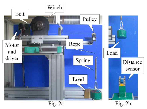
Especially, in this paper, we consider that the moving range of mass (load) is constrained in the specified value. Because the author design a control system to suppress the vibration and obtain a desirable control performance in the loading and unloading process which are operated in short distance and is final operating(work) process.
In the experimental apparatus, a spring is inserted between the pulley and load on purpose as shown Fig. 3. It is to consider the dynamic characteristic when the rope is long and extended in real condition. There is no doubt about this assumption.

The data acquisition program is utilized in labVIEW language 9.0. National Instrument PCI 6259 card is used to communicate between motor driver, encoder, distance sensor and experimental computer. The specification of the experimental apparatus is depicted in Table 1.
Table┬Ā1
Specification of experimental setup
The main object of crane work is moving the load in the vertical direction as illustrated in Fig. 2 and Fig. 3. And the authors assume that the crane system is fixed on the land site. The winding winch is located at the top of the crane and works as a main actuator to control the load position and suppress the vertical vibration.
The vertical rope dynamics due to the load moving can be calculated and approximated by the spring-mass-damper system. Exactly describing, it is estimated from the unwinded rope length Zr and the load variation Zp measured by distance sensor.
2.2. Estimation of motor-winch dynamics based on experimental data
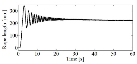
In this paper, the motor-winch system dynamics is estimated by the Matlab Identification Toolbox and described as a linear transfer function. For this, at the first step, a chirp signal with frequency variations (from 0.01 Hz to 3 Hz in 60 seconds with 3 volts) is used to excite motor-winch system. Then the output is the rope length unwinded from winch as shown in Fig. 4 and Fig. 5. As the second step, we check the accuracy level of models by tuning the parameters and orders to obtain a representative model. For examples, the authors predefine the numbers of poles and zeros. With specifying poles and zeros, the fitting ratio between real system and models can be automatically calculated by using Matlab Tool as shown in Fig. 6 and Table 2.
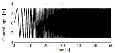
Fig.┬Ā5
Output signal(rope length variation denoted by Zr in Fig. 3) of motor-winch system for the input signal given in Fig. 4
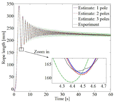
Table┬Ā2
Fitting ratio of various motor-winch models for real plant
| Model | Fitting ratio (%) |
|---|---|
| 1 pole | 76.28 |
| 2 poles | 97.43 |
| 3 poles | 94.34 |
Based on the comparison results, the authors choose the second order transfer function as the motor-winch model. As shown in Fig. 6 and Table 2, the second model is best one such that the identified model is obtained as follows:
Where zw denotes the rope length, and u denotes the control input.
2.3. Load motion dynamics
To identify load motion in vertical direction, the Newton/Euler method is introduced. Hence, it holds that:
According to Moon et al [11], while the crane moves the load in a vertical direction, the parameters of rope are time-varying and strongly depend on rope length. Then parameters for describing the rope dynamics are represented as following:
where
The overall normal rope length lr is the distance between the winch and the load, and changed by winch operating which also affects the rope parameters as shown in Eq. (5).
Where Lr (0) is the initial value of rope length.
And, it is assumed that the mass of rope is divided into two equal parts which are accumulated partly to the load and halfway to the winch. Then, an equivalent mass m in vertical motion is obtained as follows:
Where ml is the mass of load hung on to the end of rope.
Controller design
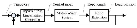
The authors introduce the control method based on an input/output linearization method for load position control as shown in Fig. 7.

Based on Eqs. (1)Ōł╝(7), the state space equation for load motion can be expressed. Before forming the state space equation of this nonlinear system, it is necessary to define state variables. Let us define the states as follows:
Where x1 is the rope length, x2 is the winding/unwinding rope velocity, x3 is the load position and x4 is the load moving velocity.
The state equation is created with previous kinetics equations and the state definitions defined by Eq. (9).
Following Eqs. (4)Ōł╝(5) in Section 2.2, the spring stiffness k, damping constant d of the rope and equivalent mass m can be calculated by changing length of rope.
However, the parameters er and ╬▓ of the rope used in experiment are hardly measured, and the length of the rope changes in the short operating range. Then, the authors assume that the damper constant d is neglected. And a spring (with stiffness coefficient kr) is inserted (between the end of rope and the load) to consider rope extension made by moving up and down the load. It is illustrated in Fig. 2 and Fig. 3.
With the assumptions and considering the inserted spring, then the equivalent mass m can be re-calculated as follows:
also, the Eq. (10) can be written as follows:
In the input-output linearization theory, the SISO system is said to have output relative degree rg in a region Rn if ŌłĆxŌłłRn as follows:
with
In Eq. (18), Lgh(x)u = 0. Then, y ╦Ö = L f h ( x ) y ┬©
Clearly, following the model given in Eq. (9), the order of the system is 4, and the output relative degree is 4 (rg = 4).
It can be seen that from Eq. (24), the control law is derived via the input-output linearization method and written as follows:
Where yref denotes the target trajectory input. k0,k1,k2 and k3 are state feedback gains. And the dynamics of the closed-loop tracking error er is given by:
The dynamics of tracking error er can be represented by state-space form where the state vectors are defined as follows:
As easily verified, system (29) is controllable. Then the state feedback gains (k0,k1,k2 and k3) can be designed by using any linear control design technique, such as the LQR design which minimizes the cost function.
Experimental results
In this section, the experimental results with proposed controller are presented with comparison study.
The proposed control system is represented by Fig. 8.
4.1. Load motion dynamics
In this paper, the stiffness coefficient kr is identified by experiment result shown in Fig. Ōł╝Fig. 11. As previously mentioned, a spring is inserted on purpose to consider rope extension which may be made by moving up and down the load in the real case.
At first, letŌĆÖs try to identify the spring dynamics with stiffness. For this, the test signal shown in Fig. 10 input to the motor-winch system. In the result, as the responses, the winching force, load position and rope length variation are illustrated in Fig. 11 and Fig. 12, respectively. It is clear that a rope model with load is represented as bellows:
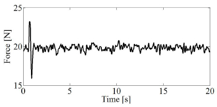
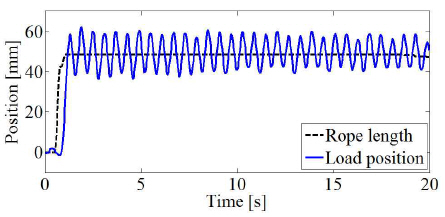
Fig.┬Ā12
Load position and rope length variation (simulation results using estimated parameter values, uncontrolled case)

Using the experiment results shown in Figs. 9Ōł╝11 and Eq. (32), the spring stiffness coefficient kr can be identified Then, the stiffness coefficient kr is obtained as bellows:
With the calculated stiffness kr about the inserted spring, the load position and rope length variation can be calculated as shown in Fig. 12 where the same test signal given in Fig. 9 is used.
Then, letŌĆÖs check the comparison results. The simulation and experiment results are shown in Fig. 13 which is uncontrolled cases.
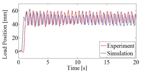
It is clear that the obtained model for real plant is acceptable and useful for control system design.
4.2. Controller design for load motion control
Based on the previous result, the authors conduct experiment for controlling load position and suppressing vertical vibration of load in the scaled crane system.
In the experiment, the feedback gains given in Eq. (30) are calculated as k0 = 2000, k1 = 1800, k2 = 1060 and k3 = 105.
And, the reference trajectories are given as two types for evaluating the designed control system. Exactly describing, the first case target trajectory is step type and another one is ramp type with defined slew rate.
More precise informations are described in Table 3.
Let us evaluate the experiment results of the first case(without slew rate).
Table┬Ā3
The input trajectory
| Case | Load target position [mm] | Target trajectory slew rate [mm/s] |
|---|---|---|
| 1 | 100 | 0 |
| 2 | 100 | 50 |
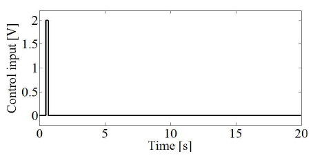
Fig. 14 shows the load position control performances when the reference target is given by step type. Where, (a) is the control input, and (b) shows the rope length released from the winch. Finally, (c) illustrates the controlled (solid line) and uncontrolled load position (dashed line). However, for the step type target trajectory, the proposed control system makes good control performance without any residual vibration in the steady state.
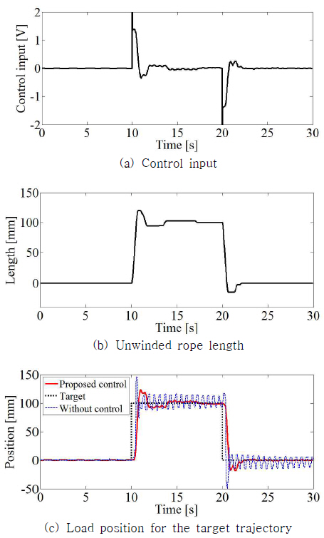
But, in the uncontrolled case, the residual vibration is continuously shown and needed to be suppressed.
In the second try(with slew rate 50[mm/s]), let us check time response with ramp type reference target trajectory. In fact, it is general that the reference signal is given by ramp type with proper slew rate for real system. With considering of real operating condition, the authors obtained experiment results which are illustrated in Fig. 15.
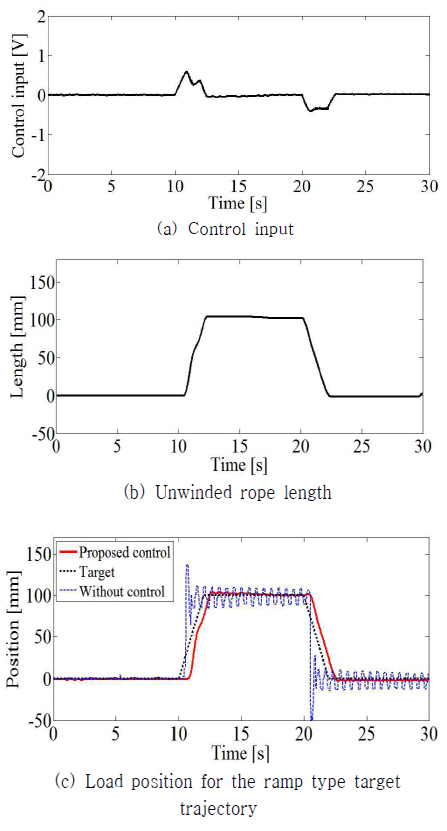
As we can see, there is no notable difference comparing with previous results in the steady state. But, we can find out more improved transient response in the proposed control scheme as expected.
Conclusions
In this paper, the authors investigated a control strategy for controlling load position and suppressing vertical vibration in offshore crane system under external factors such as rope extension etc.
Especially, it is considered how we can move a load and place it on the specified place using offshore crane system which are installed on the marine vessel.
Furthermore, there exists strong spring coefficient due to rope extension which is a key factor of undesirable load vibration. Therefore, the accurate winch system control and vibration suppressing of hanged load is necessary.
To obtain a solution for this issue, the authors designed a control system using input-output linearization method. The experimental results indicated that the proposed strategy works well and can be implemented to the real system.
 PDF Links
 PubReader
 Full text via DOI
 Download Citation
 Print
Print