A Study on the Hydrostatic Mooring Stability of Submerged Floating Ellipsoidal Habitats
Article information
Abstract
Underwater architecture in providing a comfortable living space underwater is mandated to survive prevailing environmental loads, especially hydrostatic ambient water pressure exerted on the structure of individual habitat hulls at depth and hydrodynamic fluctuation of external forces that perturb the postural equilibrium and mooring stability of the underwater housing system, for which the design including the hull shape and mooring system constraint the responses. In this study, the postural stability of a proposed underwater floating housing system with three vertically connected ellipsoidal-shape habitat hulls of different sizes are theorized and calculated for hydrostatic stability, using MATLAB in the volumetric integration of a hull and the weight of operational loads under assumed scenarios. The assumptions made in the numerical method to estimate the stability of the habitat system include the fixed weight of the hulls, and their adjustable loads within operational limits for the set meteorological oceanic conditions. The purpose of this study was to numerically manipulate a) The buoyancy and b) The adjusted center of mass of the system within the range of designed external and internal load changes, by which the effective mooring system capability and postural equilibrium requirements were argued with the quantitative analysis.
1. Introduction
The history of human accesses to underwater space have independent origins in varying disciplines. Commercial access by divers who collect useful marine biotic items such as seaweeds, sponges, pearls, and abalones beneath the water surface has been historic but still ongoing these days. To an extent, there have been more strategic accesses of the subsurface of water body mainly by those militarized nations including the proliferation of U-boats and other counterparts’ in the 20th century, followed by more autonomous submersibles since then. In civil construction, while caissoned, at the same time by accident, those workers were physiologically traumatized by accessing the sub-benthic depth at the most workplaces underneath major urban rivers for building bridges or tunnels(Dodde, 2017; Wikipedia, 2019; Butler, 2004). Underwater living space (underwater housing, hereafter) including ocean observatories, underwater restaurants, and undersea hotels for a temporary or permanent human occupancy is getting popular(Bitterman, 2013). And as more modern and integrated attempts that harness the potential values of the pelagic space from the leisurely aqua tourism to the underwater surveillance technologies, nations desire and develop offshore by building a subsea research center(KIOST, 2016), which would become an introductory phase of more common usage of the pelagic ocean space for human residence. For a submerged and floating civil structure in the world however, the case is rare and limited as the engineering study on SFTB(Submerged Floating Tube Bridge) across Norwegian fjords (Lothe, 2015).
Although dynamics of a floating body, especially with long and thin hull shape have been studied thoroughly on their movements in 6 degree of freedom (Sohn, 2014; Fossen, 2002), underwater habitat system proposed in this study as a space for permanent human residence can add new aspects into the underwater floating housing system, which consists of multiple hulls (in its scalability aspect) of ellipsoidal shapes (in its simplicity aspect) with the different sizes of their principal semi-axis of (4m, 4m, 3m) for 3-man, (6m, 6m, 3m) for 8-man, and (9m, 9m, 3m) (in its diverse applicability aspect) for 20-man use (see Figure 1). As a submerged floating housing system, understanding its postural equilibrium and mooring stability becomes an apparent research goal. The operational interior pressure of these hyperbaric hulls is assumed adjustable within the pressure range between 1ATA(atmospheric absolute) and the ambient pressure at their installation water depths; therefore, a diver excursion outside the habitat through either a moon pool or airlocks can be adopted as a part of underwater activities.

Underwater floating housing system (habitats)
The mooring system of the vertically combined three(3) habitat hulls and its stability are considered under hydrostatic conditions only. Although its hydrodynamic stability should be considered at well-specified operational and environmental limits, at this current and front-end of design development stage, both the main hull design factors including fixed- and adjustable-load of the hulls and the operational load limits of the proposed semi-autonomous underwater floating housing system are to be estimated based on the hydrostatic response. The level of technical difficulty in this case is primitive, so that the design of the underwater housing system can be justified only for the proposed initial design criteria that takes the assumed and minimal operational complexity into account and keeps the numerical simplicity during the calculation of buoyancy and working loads.
This (semi-)autonomous type of submerged floating housing system requires efficient living space management and also reliable means to store resources and materials to support human life at depth, while the currently prevalent non- /semi-autonomous habitats largely depend on the open and continuous supplies of resources by maintaining their physical connection with the external atmosphere utilizing a vertical tube or a semi-horizontal tunnel. To select a compatible set of the design basis for a placeable underwater floating housing system, its preliminary designs are numerically tested utilizing MATLAB, and analyzed for both the mooring stability including individual and combined buoyancy characteristics of the hulls, and the hydrostatic equilibrium-restoring (anti-roll) tendency constrained by the buoyancy characteristics of the hulls at the specified mooring conditions in the following chapters.
2. Proposed underwater housing system
The proposed underwater floating housing system is a type of underwater habitat with ellipsoidal hulls of different size, floating and being moored by ropes to six(6) anchor piles on the seabed indicated by large triangles (see Figure 1). Blue arrows show increasing ambient water pressure from the water surface to the depth.
The nominal volumes of the hulls of the submerged floating housing system and their expected amounts of water displacement are 250, 500, and 1,000 cubic meter for the hull of 3-man, 8-man, and 20-man nominal occupancy, respectively.
For the simplicity of calculation, the possible additional water displacement due to external equipment connected outside the ellipsoidal hull is ignored. The weight of the individual hull is calculated for the thickness options of 1mm, 10mm, and 100mm of HY-100 carbon steel plates with its cardinal density of 7,748kg/m3(Aung, 2007). The load distribution by the interior formation inside a hull is assumed to be a ‘fixed weight’ of the interior equipment, while the transitional weight of occupants on-board and material planned corresponding to a set 14 day stay period underwater to be termed as the ‘adjustable weight’.
3. Mooring stability calculation
The main objectives of the mooring stability calculation are to seek a primitive but numeric justification on the underwater floating housing system and its buoyancy design by manipulating both proposed volume and load structures, and to define the quantitative scale of horizontal lean for each individual hull responding to the premised external and internal load perturbation. The calculation input factors of air weight, fixed-weight, and adjustable-weight of each hull are defined with the rationales claimed in Table 1, where the assumptions of the conditions for life/living support are selectively chosen from the research results of Seasteading Institute(Hencken, 2013).

Specified load factors in buoyancy calculation adjustable loads of the hulls).
3.1 Fixed load estimation
The fixed weight of a habitat hull consists of its volumetric weight based on the specified hull thickness and its interior equipment weight although the density distribution of each may differ. At the current and initial stage of habitat system design development, the external load contribution by the weight of mooring equipment and other peripherals can be ignored on behalf of the simplicity of its buoyancy calculation. The density of HY-100 steel plate for the hulls is 7,748kg/m3, while the ad hoc density of interior equipment made of carbon steel alloy is assumed to be 7,850kg/m3. Although the volume claimed for the interior equipment is less likely to have a uniform density of the suggested carbon steel for its entirety, to initiate this front-end-engineering, throughout the following buoyancy calculation, we assume that the interior equipment is uniformly distributed on the vertical axis of the ellipsoid (or point-distributed at the center of the hull) without affecting the natural center of mass. For the mooring stability and postural equilibrium calculation during the second half of the calculation, it is also assumed that the volumetric density distribution of the interior equipment is vertically uniform and distributed under the specified horizontal surfaces of c= 0m, -1m, or –2m of the specified ellipsoids (see Table 5).

Calculated leans of the hulls
3.2 Adjustable load estimation
The assumptions of these rationales in selecting the adjustable loads for the hulls of 3-man, 8-man, and 20-man occupancy of the underwater floating housing system account for the basic life support provisions including water, food, and other necessary materials, for which the set input values follow the guidelines by Seasteading institute(Hencken, 2013). On behalf of the simplicity in this calculation, each person on-board is assumed to be allowed a 30kg of personal cargo with the specified amounts of water and materials for his/her planned 14 day stay period inside the habitat (see Table 1 for input values including Table 1 Specified load factors in buoyancy calculation adjustable loads of the hulls).
3.3 Mathematical method
MATLAB is utilized to calculate volumetric characteristics of the ellipsoidal hulls. The function ‘ellipsoid’ of MATLAB generates three(3) (n+1) by (n+1) dimensional meshes of a hull with the principal semi-axis of a= 4m, b= 4m, c= 3m for 3-man; 6m, 6m, 3m for 8-man; 9m, 9m, 3m for 20-man habitat hull respectively, where ‘n’ is a user input value to set the accuracy of the numeric model by choosing the data size of those volumetric meshes. The volume calculation conducted by linear multiplication among ‘a’, ‘b’, and ‘c’ component of the hull meshes of each ellipsoidal hull with the specified thicknesses of 1mm, 10mm, and 100mm are compared to the reference volumes calculated alternatively, utilizing the function ‘alphaShape’ of MATLAB for the soundness check of the volume integration.
4. Analysis
The resulting buoyancy values of each habitat hull under hydrostatic condition have calculated based on the initial assumptions of their fixed weights, then the concatenated adjustment of those if the initial assumptions have failed for the underwater housing system to reach a desired positive buoyancy range. The center of mass is calculated with the specified volumetric density distribution of the fixed weight of a hull. The degree of lean for each hull is then calculated.
4.1 Positive buoyancy as mooring stability factor 1
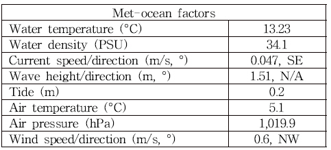
The water density of 1,034 PSU at the candidate installation location, as the only affecting meteorological oceanic condition at the presumed installation site of the underwater floating housing system, is used from the observation made by Korea Hydrographic And Oceanographic Agency from Busan tidal station(35.1 N, 129 E) at 19:55 March 22nd 2019. Other met-oceanic variables collected on the date are specified in Table 2.

Meteorological oceanic conditions for installation
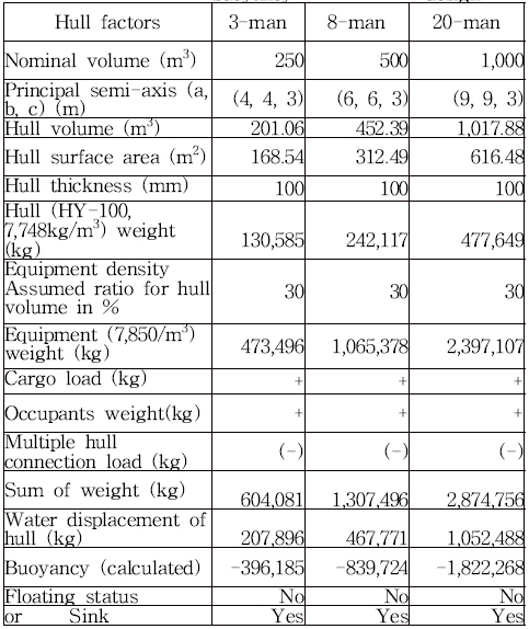
The ‘hull weight’ is calculated by multiplying the hull thickness volumes with its density. Buoyancy calculations of each hull are done in both Table 3 and 4 below. The estimated buoyancy for the initial design(see Table 3) shows that the underwater floating housing system fails to float but sink. Assumed specification and load factors in buoyancy calculation of the hulls with their principal semi-axis (a, b, and c), where ‘a’ and ‘b’ represent horizontal and ‘c’ vertical component. The signs of ‘+’ and ‘(-)’ indicate the qualitative influence expected to the resulting buoyancy without specifying the magnitude for the simplicity of calculation.

The estimated buoyancy for the initial design

The estimated buoyancy for the adjusted design
The resulting buoyancy values of the underwater housing system with the initial assumption on the fixed weight equivalent to a 30% of water displacement of each hull are all negative; therefore, the initial assumption of the system has failed to support its principal design criteria of being float. Therefore, concatenated adjustment to the initial assumption on the fixed weight has applied for the ratio of the interior equipment weight to meet the specified volumetric percentages of 4%, 5%, and 6% of the water displacements for 3-man, 8-man, and 20-man hull, respectively (see Table 4). The adjusted equipment weights for each hull make the system float.
The resulting buoyancy outcomes of 14,178kg, 48,091kg and 95,418kg show all positively buoyant hulls for 3-man, 8-man, and 20-man occupancy, respectively; therefore, the required mooring tension of the underwater housing system connected consecutively as in Figure 1 is equal to the linear sum of the buoyancy of each hull, 157,687kg.
4.2 Center of mass and equilibrium restoration as mooring stability factor 2
For the floating ellipsoidal underwater housing system with its proposed installation into a fully submerged pelagic space utilizing the six(6)-tension leg mooring ropes to the piles on the seabed as animated in Figure 1, the center of buoyancy is located at the center of each ellipsoid due to the geometric symmetry of the hulls. As it is the case of a boat, a fully submerged habitat system is also subject to both external and internal kinematic perturbation against its postural equilibrium (stability), where the tendency of its postural restoration from the state perturbed is blatantly affected by the locations of metacenter of each hull, although the submerged floating housing system does not have any freeboard when the system is underwater. The distance GM between the center of mass(G) and the center of lean, metacenter(M, which is most likely assumed to be at the center of the ellipsoid), becomes the governing parameter for the level of lean (stability) of each hull.
In a semi-static aspect, the restoring force on an externally perturbed hull will work against the current and momentary lean and restore its postural equilibrium in the course of damping oscillation without having any permanent shift of its original center of mass. The magnitude of the restoring force is proportional to the degree of the lean perturbed and the designed magnitude of GM.
On the other hand, when there is a shift of internal mass of ‘adjustable load’ due to any shift of occupants or material inside, such an internal perturbation of mass shall not generate restoring force, rather incur a shift of the original center of mass to a new location that justifies the lean and offsets the previous shift of the relevant mass. In Table 5, the magnitude of leans for the shifts of ‘adjustable load’ from the original center of hulls (at the center of each ellipsoid) to 3m, 5m, and 8m aside and ideally dot-distributed on the horizontal principal semi-axis (either the axis of ‘a’ or ‘b’) of the 3-man, 8-man, and 20-man hull, respectively. In consideration of designing a compatible postural stability of the submerged floating housing system, differing conditions of ‘fixed weight’ density distribution (from c = 0m, c = -1m, and c = -2m position on the vertical principal semi-axis to the bottom of c = -3m) of the 3-man, 8-man, and 20-man hull are calculated and compared, respectively. The volumetric contribution of these additional fixed loads by differing conditions above are calculated simultaneously by both multiplying the absolute values of the distance vector components of the thickness mesh of the hull (Vt_xyz) and utilizing function ‘alphaShape’ (see Vt_α in Table 5) to check the soundness of the numerical methods applied for volume integration.
In Table 5 a hull with a larger horizontal principal semi-axis, i.e, 20-man hull, shows apparently a bigger degree of lean compared to a more circular hull shape of a 3-man occupancy. For each hull when the location of the center of mass is near to the bottom of the hull, the degree of the lean due to the shifted application of adjustable load is minimized, showing an increased postural stability.
In general, both the centers of mass and the centers of buoyancy for the proposed underwater floating housing system prior the shift of internal mass of ‘adjustable weight’ are assumed to be located near the vertical center, c = 0 of each hull. The new centers of mass ‘Center of mass adjusted’ in the table with the specified amount of internal mass redistribution appear at new lower, but horizontally at the central, locations on the vertical principal semi-axis of ‘c’. The magnitude of a lean is greater for the hull with a larger horizontal dimension of principal semi-axis because of the enhanced effect of the horizontal leverage.
For a hull of 20-man use, as an example, the deviation from the initial postural equilibrium caused by the assumed operational mass shift of ‘adjustable load’ from the center of the ellipsoid to the location a= 8m (or b= 8m) on the horizontal principal semi-axis, acting as the idealized dot mass, the degree of lean is smaller when the ‘Center of mass adjusted’ is redesigned further away from the natural center of the ellipsoid toward the bottom of the ellipsoid, i.e. as the lean angle of 5.2604 degree with its ‘center of mass adjusted’ is at the nearest location of c= -1.7673m with the uniformly distributed ‘fixed weight’ of the interior equipment over the volumetric region between c= -1.7673m and -3m (as indicated ‘c= -1.7673m↓‘ in the table), the same hull with the farthest ‘center of mass adjusted’ at c= -2.4355m↓ shows the smallest lean angle of 3.8223 degree.
5. Results
Although the stability design of any hull structure in naval architecture shares some principles of hydrostatics, the submerged floating housing system and its hull design deviate from the typical nature of a vessel (thin and long) hull, for which the formation of freeboard (indicated by ‘f’ in Figure 2) and metacenter(M) are critical for providing extra buoyancy and restoring the postural equilibrium, if disturbed. However, when the submerged floating housing system is installed at depth and submerged entirely, there is no remaining freeboard; therefore, the system becomes vulnerable in maintaining postural equilibrium against any external perturbation. Moreover, the internal mass shift within the operational range will work as a different type of postural perturbation, which does not trigger corresponding restoration of the equilibrium compared to the restoration following the external perturbation (see Figure 2).

Leans compared between a boat (Wikipedia, (2019)) and a habitat hull
Considering the ratio of the hull height(depth) to the breadth and the relationship between the center of mass ‘G’ and the center of buoyancy ’B’, the geometric formation of the metacenter ‘M’ of the habitat hull with larger horizontal principal semi-axis, i.e., 20-man occupancy, has smaller distance of GM and BM, providing relatively shorter righting arms and the weaker tendency in postural restoration compared to those of a boat. The current numeric test on the hydrostatic stability of the submerged floating housing system suggests that the proposed hull system can physically harbor the center of mass near to the bottom of each hull and uphold the enhanced stability characteristics by designing a GM of 1m or larger, for which DNV GL(Det Norske Veritas and Germanischer Lloyd) code and regulation mandates GM to be greater than or equal to 0.5m for ordinary vessels, and 1.0m for any semi-submersible(Lee et al., 2000).
Among the factors of six(6) degree of freedom, the linear movements of surge, sway, and heave are designed to be managed by the horizontal and vertical tension incurred by the positive buoyancies of the proposed mooring system while the angular motions such as roll (pitch) and yaw can be only partially constrained by the same mooring system. To enhance its postural stability against roll (pitch) and yaw of the proposed underwater floating housing system, an instrumental aid based on realtime monitoring of the lean of a hull with counter-weighting (or counter-balancing) mechanism is recommended.
For a full-scale stability response simulation of the proposed submerged floating housing system with three(3) vertically connected hull complex, the hydrodynamic response analysis is desirable to achieve a realistic and analytical representation of its buoyancy design and mooring system requirements. The assumptions on this hydrostatic analysis shall be further diversified upon the required functional capabilities of the system in the hydrodynamic response simulation; therefore, each technical mandate assumed and applied in the current study shall be verified further for more realistic quantities and scales in dynamic operational environment. Several operational scenarios of external stability perturbation and internal load fluctuation shall also be taken into account, covering a thorough process of the habitats’ fabrication, lifting, loading, transportation, installation, and de-mobilization at the likely locations of installation under both the ordinary operational and extreme sea states. This hydrostatic response analysis for the submerged floating housing system is keen to capture the principal physics of hydrostatic re-equilibrium at the beginning stage of its design basis development, and provides a firm anchoring for the upper level research including hydrodynamic analysis utilizing OrcaFlex, software for the hydrodynamic simulation of oceanic marine systems.
Acknowledgments
This study was funded by the LINC+ of the Ministry of Education. (ICT integrated Smart Underwater Housing Design Technology, Project No. 2019-E-G034-010109)