


1. Introduction
In recent years, shipping has increased due to the development of the industry and freight transport. To reduce the price of shipping, the ship is designed bigger to transport more goods at a time. However, the ship berths at various ports to loading and discharging goods during its voyage. Therefore, the ship usually operate in various loading conditions depending on site condition and other factors. To ensure that the ship has good maneuverability in given loading conditions such as the turning ability and course keeping ability, it is necessary to investigate the hydrodynamic forces acting on the ship hull.
In the past, researchers were researching the hydrodynamic forces acting on the ship hull by performing numerical simulation or captive model test. Lee (2003) predicted the hydrodynamic forces in laterally berthing maneuvers using Computational Fluid Dynamics (CFD). Park (2018) investigated the effect of the vertical center of gravity on the hydrodynamic force acting on the ship hull. The numerical method was performed in various drift angles to estimate the hydrodynamic forces. Nguyen (2019) studied the hydrodynamic forces acting on the ship hull with and without a propeller by performing a model test. In addition, the hydrodynamic forces in the regular waves were estimated. Dai (2019) estimated the hydrodynamic forces and hydrodynamic derivatives of the KVLCC2 by a virtual captive model test. The Oblique Towing Test (OTT) and Circular Motion Test (CMT) were carried out to estimate the hydrodynamic forces. Wang (2011) estimated the hydrodynamic forces in oblique motion through experiment and numerical method. The effect of the drift angle was investigated. Islam (2018) estimated the linear hydrodynamic derivatives using static drift simulation. The result of the simulation of hydrodynamic forces was compared with experimental results. RANS based solver and SHIP_Motion were used for the simulation. Yang (2019) investigated the hydrodynamic forces of the KVLCC2 model in various drift conditions by numerical method. In addition, the effect of the mesh conditions on the hydrodynamic forces was considered in that study.
In our study, the effect of loading conditions on hydrodynamic forces acting on the ship hull in various loading conditions is investigated. After that, the hydrodynamic derivatives are estimated based on the estimated hydrodynamic forces obtained by performing experiments for each condition. The Korea Autonomous Surface Ship (KASS) was selected to perform captive model test. This test is carried out at towing tank of Changwon National University to measure the hydrodynamic forces acting on the KASS. In actual ship, the loading condition was determined based on loading as full loading, half loading or ballasting. However, in this study, the loading condition considered in this study is determined based on the draft, which is decreased by 5 percent for each loading condition. The static test as Oblique Towing Test (OTT) and Circular Motion Test (CMT) and Circular Motion Test with Drift (CMTD) are performed in the various loading conditions. OTT and CMT are performed to measure the hydrodynamic forces acting on the KASS model in oblique moving and steady turning, respectively. The hydrodynamic derivatives related to sway velocity and yaw velocity are estimated based on OTT and CMT results. In order to determine the coupling coefficients of sway velocity and yaw velocity, the CMTD is performed. The hydrodynamic forces in the OTT are compared with the result of other institutes in the case of the full loading condition. Then, the effect of the drift angle and yaw rate on the hydrodynamic forces are evaluated. The changing of the hydrodynamic forces in various loading conditions is measured and the influence of the loading conditions on the hydrodynamic coefficients is discussed. The hydrodynamic coefficients obtained from this research can be used to perform maneuvers simulation of the same ship type as KASS. The standards of maneuvers can be checked in this state.
2. Test facility and test conditions
2.1 Test facility
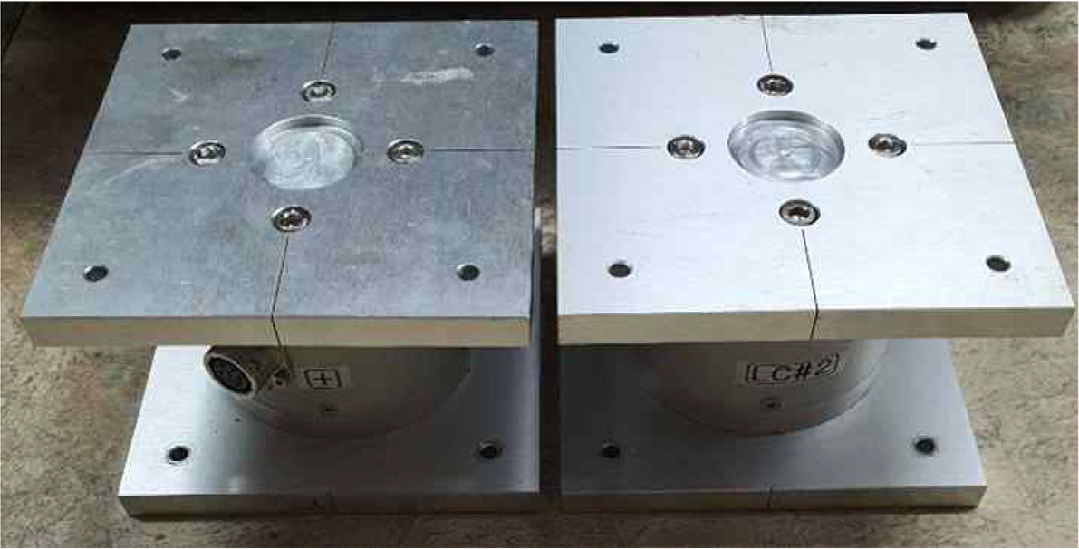
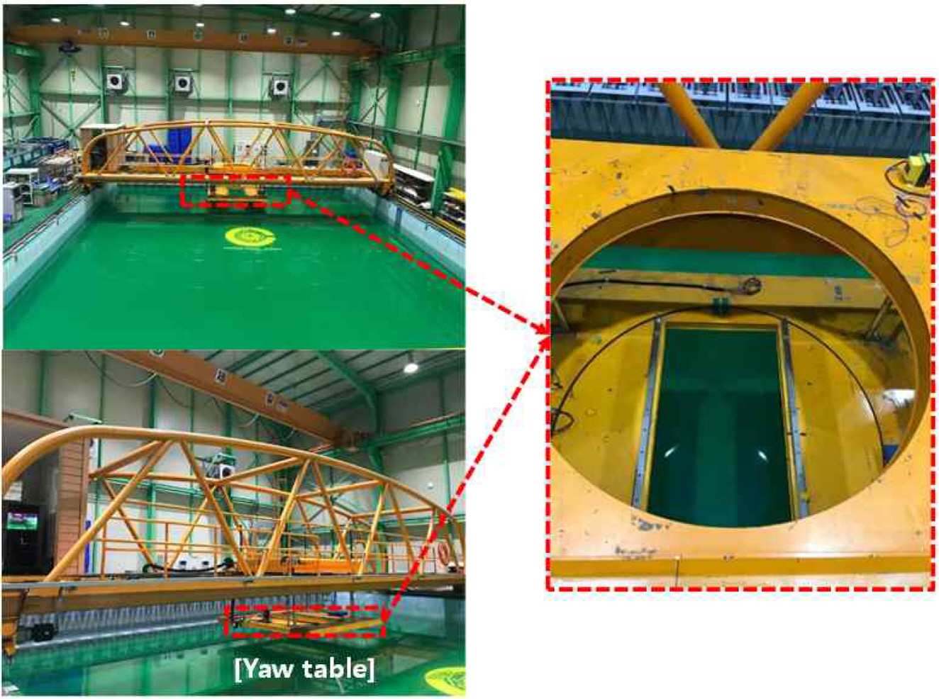
The experiment of KASS was performed in a towing wave tank in Changwon National University. Two load cells with 2-components force transducer were used to measure the hydrodynamic force acting on the KASSŌĆÖs hull. The model of the load cell is MCL-2A01-60N and the capacity of the load cell is ┬▒60N for both the force in-x direction and y-direction. Load cells that were used in this test are shown in Fig. 1. Fig. 2 shows the towing tank used in this experiment. Towing tank dimensions are 14 m breadth, 20 m long and 1.8 m deep. The limit of the carriage speed is 1.0 m/s. In this experiment, the water deep was set at 1.0 m.
2.2 Model ship and test conditions
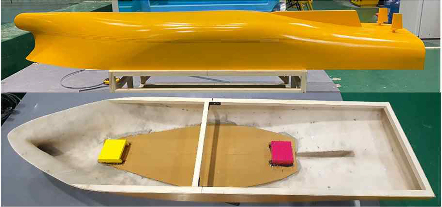
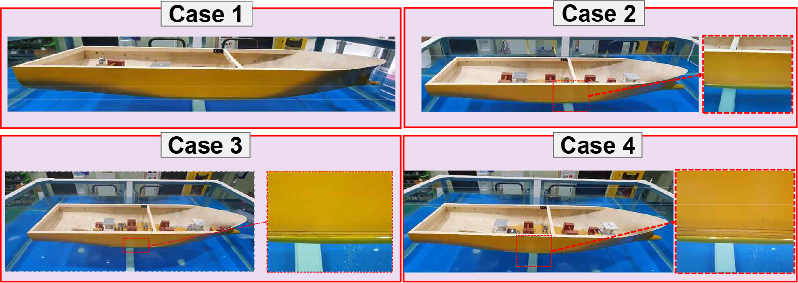
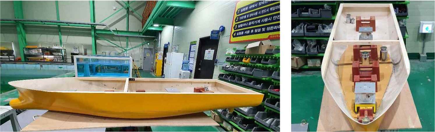
The KASS model was selected to investigate the effect of the loading condition on hydrodynamic forces. The model test was performed in various drafts to obtain hydrodynamic coefficients of the KASS model. The model test has a scale ratio of 1/11. Fig. 3 shows the KASS model used in this experiment. The principal dimensions of the both full scale and model scale are listed in Table 1. The experiments were carried out at the condition of the model scale with ship speed set at 0.931 m/s (equivalent to 6 knots in full scale). The model test was performed in the OTT, CMT CMTD to investigate the effect of the drift angle and yaw rate on hydrodynamic forces. In addition, the effect of the loading condition on hydrodynamic forces is investigated. The loading conditions are listed in Table 2. Table 3 lists the test conditions in this experiment.
3. Experiment
3.1 Equation of motion
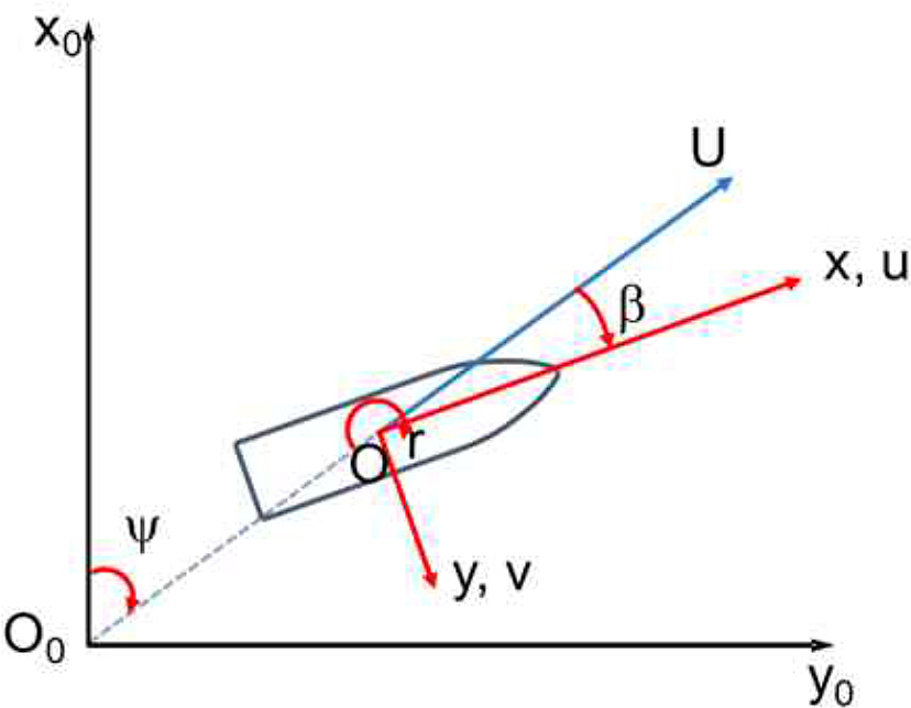
In this experiment, the shipŌĆÖs maneuvering mathematical model considers three degrees of freedom. Therefore, the surge force, sway force and yaw moment are measured. Two right-handed coordinate systems were used to describe the hydrodynamic force acting on the ship hull. A body-fixed coordinate system and an earth-fixed coordinate system are shown in Fig. 4. The mathematical model can be described by the following surge motion, sway motion and yaw motion by Eq. (1).
where X , Y and N are denoted for hydrodynamic forces acting on the KASSs hull as surge force, sway force and yaw moment, respectively. m, Izz and xG are the mass of KASS, moment of inertia in yaw motion and the longitudinal center of gravity of the ship, respectively. u and v is the velocity in x-axis and y-axis, respectively. r╠ć is the acceleration of angular.
In order to estimate the effect of the loading condition on the hydrodynamic coefficients, the hull forces are modeled based on the Maneuvering Modeling Group (MMG) model for ship maneuvering (Yasukawa, 2014). In addition, the 3rd order polynomial function is replaced by the 2nd order polynomial function and absolute value of sway velocity and yaw rate to determine the hydrodynamic coefficients as Yv|v|, Yr|r|, Nv|v| and Nr|r|. The mathematical model of the hull forces is described in Eqs. (2)- (4). The prime represents for non-dimensional value.
where XŌĆ▓vv, XŌĆ▓rr and XŌĆ▓vr are the surge derivatives. YŌĆ▓v, YŌĆ▓v|v|, YŌĆ▓r, YŌĆ▓r|r|, YŌĆ▓vvr and YŌĆ▓vrr are the sway derivatives. NŌĆ▓v, NŌĆ▓v|v|, NŌĆ▓r, NŌĆ▓r|r|, NŌĆ▓vvr and NŌĆ▓vrr are the yaw derivatives. vŌĆ▓ and rŌĆ▓ are non-dimensional sway velocity and angular velocity, respectively.
3.2 Ballasting test and inertia test
Before performing the experiment, the mass distribution of the ship was made identical to the real scale. Fig. 5 shows the ballasting test of the KASS model ship in various loading conditions. In addition, the inertia table was used to obtain the mass moment of inertia Izz. Fig. 6 shows the inertia test in full loading condition. The results of the inertia test are listed in Table 4. The differences of measured Izz and target Izz are smaller than 5%. This error value can be accepted in captive model test.
3.3 Experimental setup
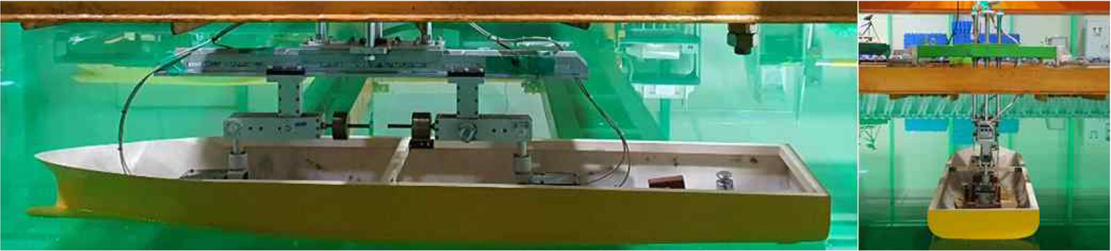
The KASS model test was carried out at the towing tank in Changwon National University. The load cells are installed on the strong back near the bow and stern of the model ship. The potentiometers are connected between load cells and the measuring frame which is then connected with the sub-carriage in the yaw table. During the test, the model test is towed by the towing carriage. The yaw table can change the drift angle by rotating around its center. In the case of the circular test, the yaw table rotates with the yaw rate that was set. The signal obtained from the load cell is then transferred from the electrical signal into the digital signal by an A/D converter NI USB-6212 was made by National Instruments Corporation Company. The surge force and sway forces are measured by the total surge force and sway force obtained from the load cells. In addition, the yaw moment is obtained by the sway force of the load cells and the distance from the center of these load cells to the center of the model ship. Fig. 7 shows the real experimental setup of the KASS.
3.4 Data analysis
The measured data is recorded as time series when the carriage speed reaches the target speed of 0.931 m/s while stable. The time series are constantly checked after each run to avoid obvious errors. The hydrodynamic forces obtained from two load cells are estimated by the mean value. X , Y and N are the hydrodynamic forces acting on the KASSs hull as surge force, sway force and yaw moment, respectively. XŌĆ▓, YŌĆ▓ and NŌĆ▓, are the non-dimensional of hydrodynamic forces acting on the KASSs hull as surge force, sway force and yaw moment, respectively. The definition of the non-dimensional hydrodynamic forces is shown in Eqs. (5) - (7).
4. Result
4.1 Validation result
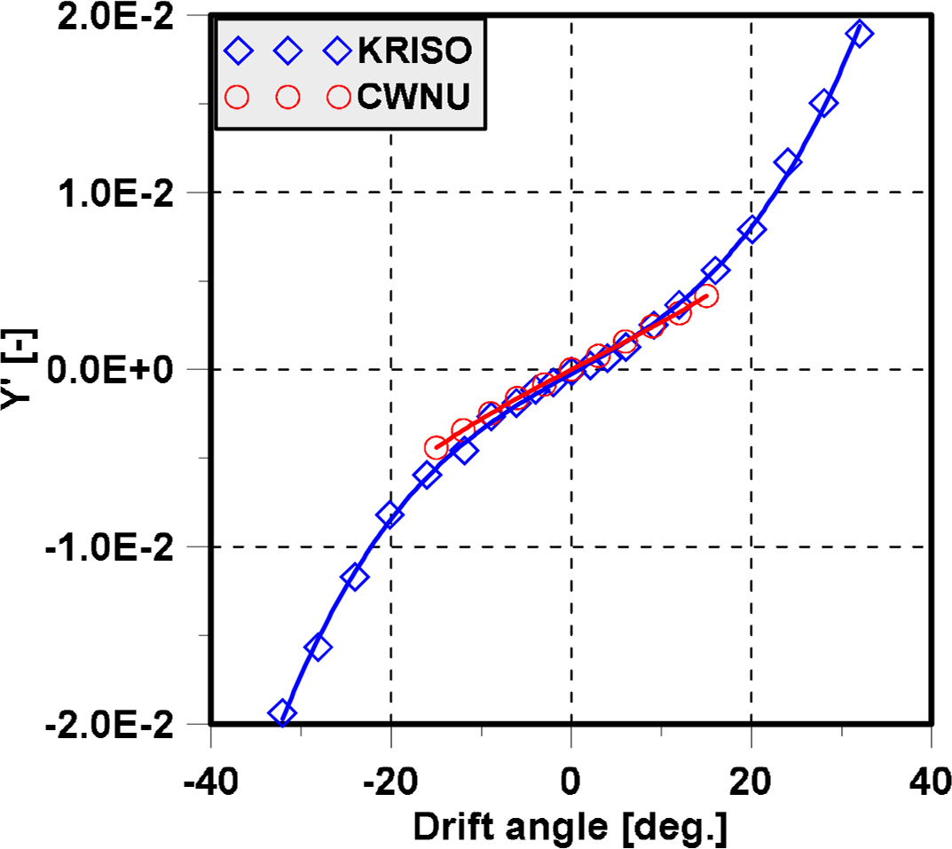
The experimental results of the sway force acting on the ship hull in the case 1 (full loading condition) are compared with the results from the Korean Research Institute of Ship and Ocean Engineering (KRISO) (Kim, 2021) as shown in Fig. 8. Sway force results are similar to the results from KRISO. In the small drift angle, the error of the modelŌĆÖs hull is barely affected. When the drift angle increase, the effect of the error on the modelŌĆÖs hull rapidly increases. In the large drift angle, there is a slight difference in sway force due to the modelŌĆÖs hull. In experiment, many thing can be affect to the result. The length between perpendiculars of the KRISOŌĆÖs model ship is 5.789 m. The length of model which used in this experiment is 2 m. In addition, the boundary layer of the KRISOŌĆÖs model is larger than our model ship. Therefore, there may a little difference between KRISOŌĆÖs result and result of the present study in large drift angle due to the scale effect.
4.2 Experimental results
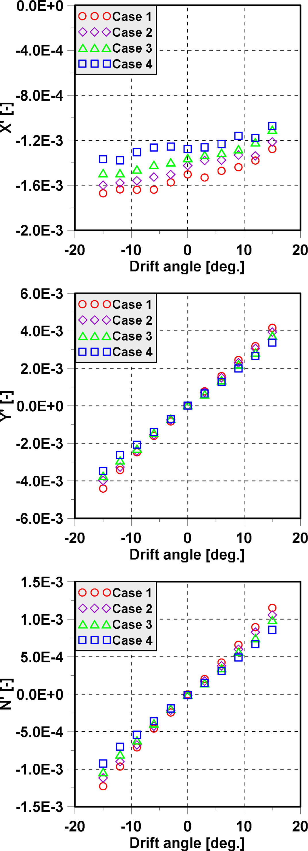
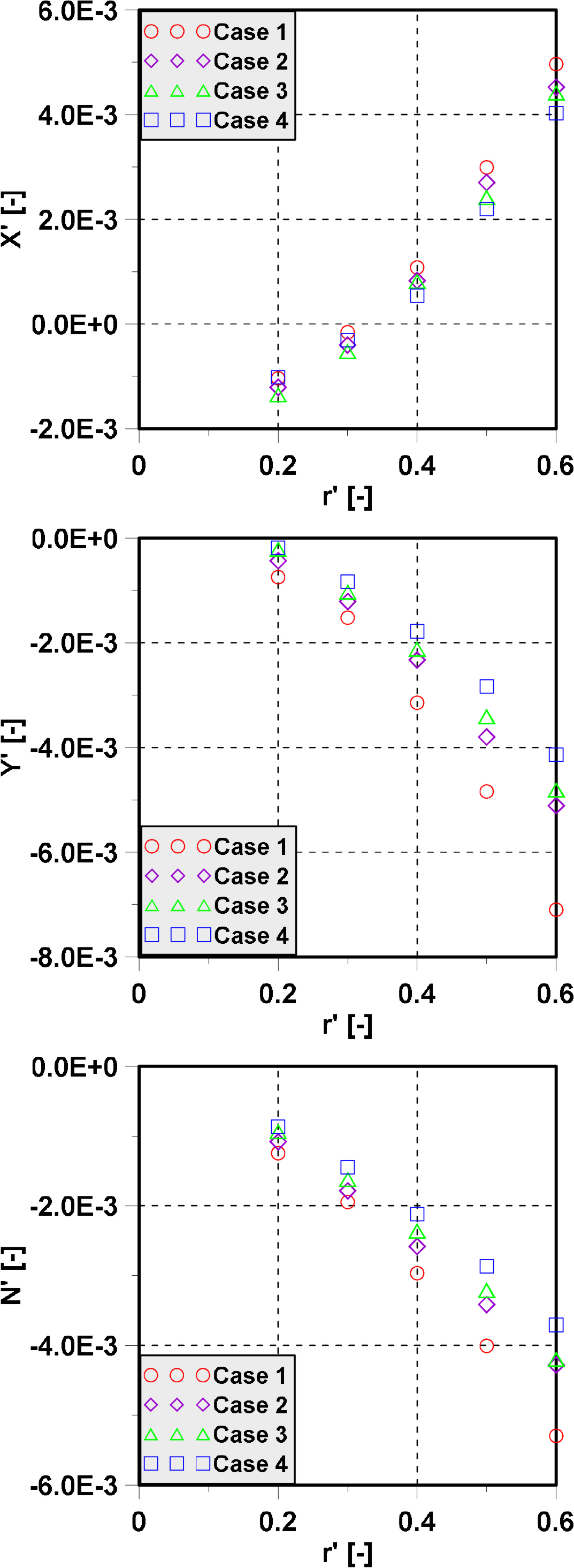
In the oblique towing test, the effect of drift angle is investigated. Besides the effect of drift angle, the effect of the loading condition is the main investigated in this study. The hydrodynamic forces acting on the model ship hull in various drift angles and various loading conditions are shown in Fig. 9. The hydrodynamic forces increase slightly in various loading conditions and its effect is shown clearly in the large drift angle. The hydrodynamic forces are large in the case of full loading condition and reduce which decrease in the loading condition. The hydrodynamic forces are affected by the fluidŌĆÖs pressure around the shipŌĆÖs hull. When the loading condition decreases, the wetted area also decreases. Therefore, the fluidŌĆÖs pressure also decreases due to the decreasing of the wetted area. The hydrodynamic forces acting on the ship hull increase significantly with increase in the drift angle. The results of the hydrodynamic forces in various yaw rates and various loading conditions are shown in Fig. 10. The loading condition also affects the hydrodynamic forces in CMT. In the case of full loading condition, the hydrodynamic forces increase dramatically and nearly 2 times of case 4. In addition, when the yaw rate increases, the hydrodynamic forces increase significantly. The changing of hydrodynamic forces in various loading conditions is affected by the wetted area and wetted volume. The wetted area and wetted volume of case 1 are 1.174 m2 and 0.0651 m3. The wetted area and wetted volume of case 4 are 0.993 m2 and 0.0509 m3. The wetted area and wetted volume decrease due to the decreasing of loading condition. In addition, the hydrodynamic forces acting on the ship hull is the water pressure acting on the wetted area of ship. Therefore, the hydrodynamic forces decrease in lower loading condition.
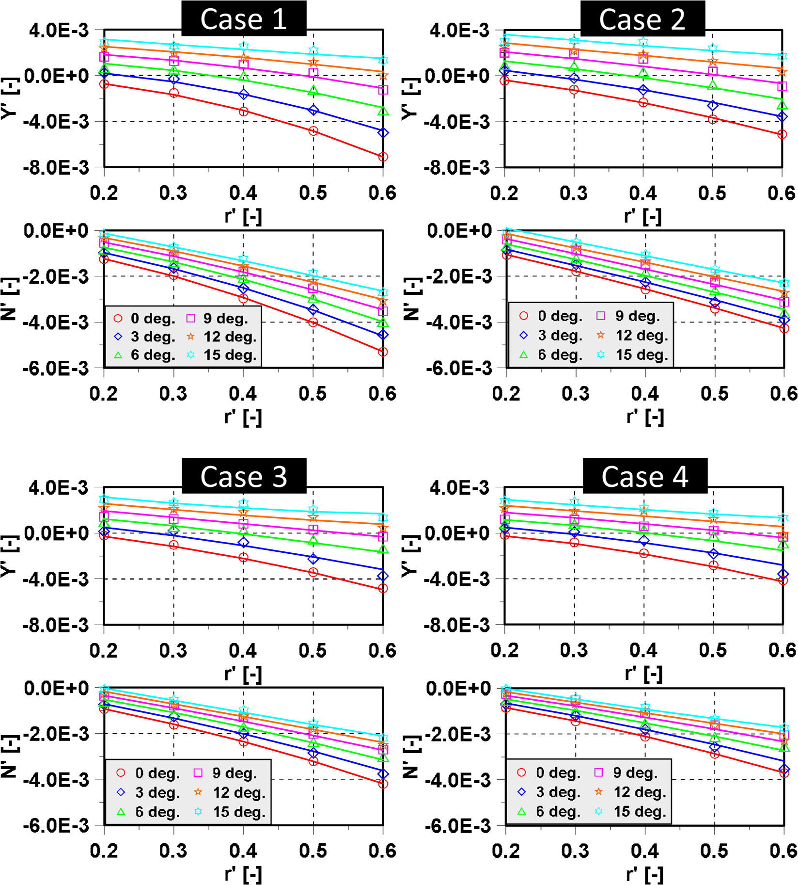
The effect of the drift angle, yaw rate and loading condition on hydrodynamic forces are shown in Fig. 11. The loading condition effect on small yaw rate is similar to trend of CMTŌĆÖs results. However, the hydrodynamic forces increase in large yaw rate due to the effect of the loading conditions. Moreover, the hydrodynamic forces reduce and become a positive value when the drift angle increases.
4.3 Hydrodynamic coefficients
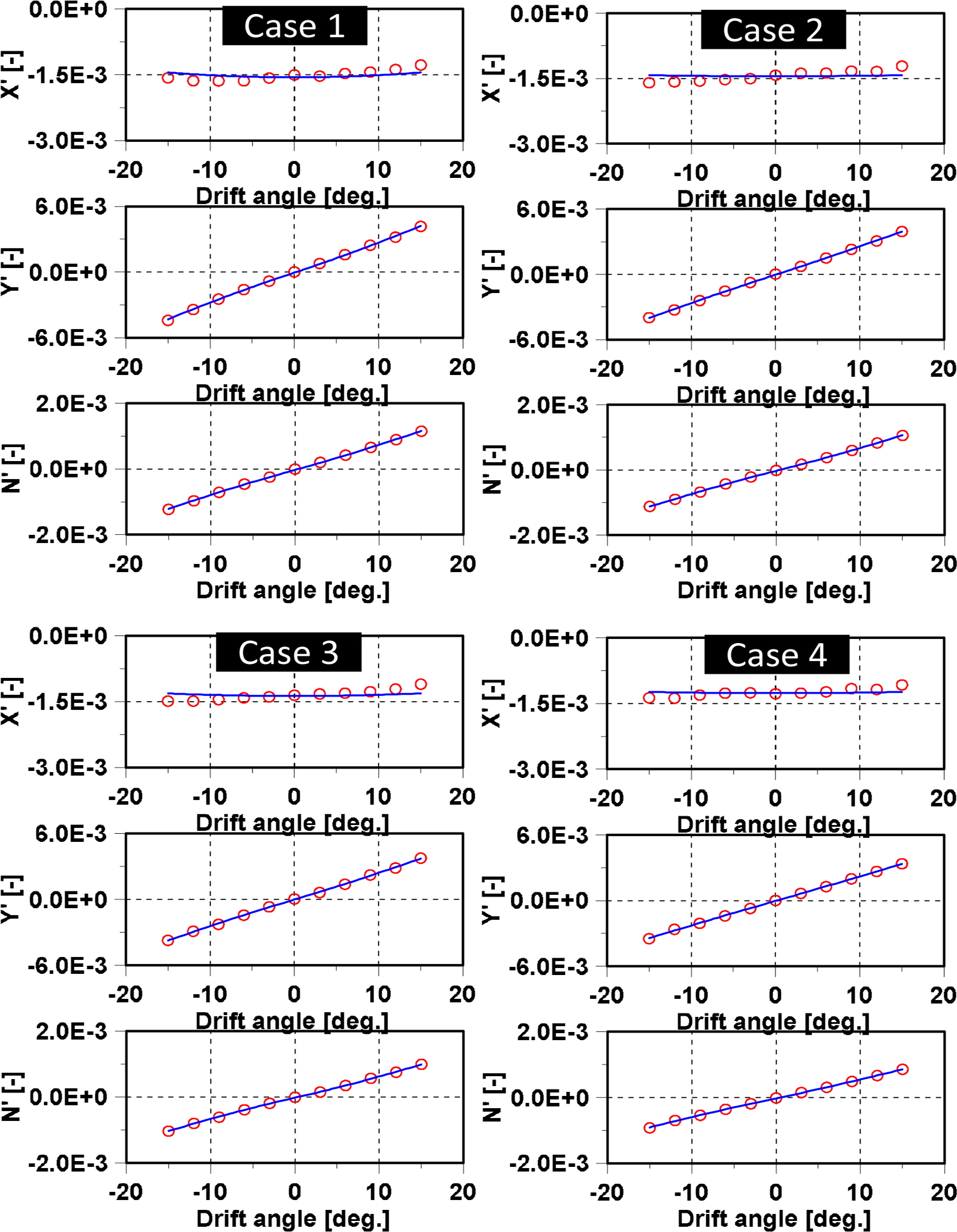
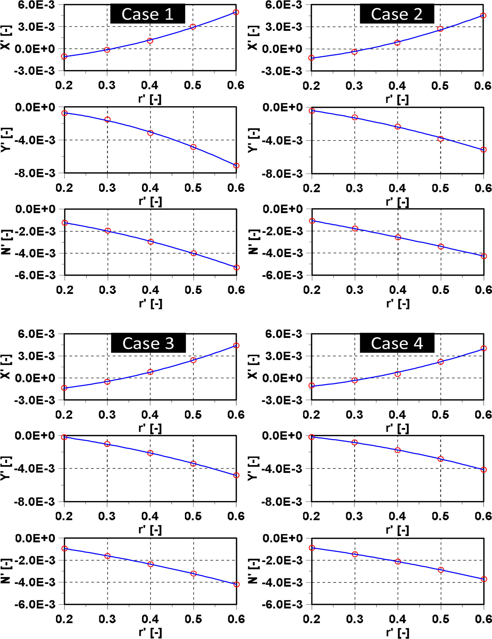
The hydrodynamic coefficients on maneuvering are determined using the OTT, CMT and CMTD results. The centrifugal force is removed in the hydrodynamic forces measured in both CMT and CMTD. Then, the hydrodynamic coefficients are estimated using the expression of the 2nd order polynomial function. XŌĆ▓vv, YŌĆ▓v, Y ŌĆ▓v|v|, N ŌĆ▓v and N ŌĆ▓v|v| coefficients are determined based on the OTT results. X ŌĆ▓rr, Y ŌĆ▓r, Y ŌĆ▓r|r|, N ŌĆ▓r and N ŌĆ▓r|r| coefficients are determined based on the CMT results. Y ŌĆ▓vvr, Y ŌĆ▓vrr, N ŌĆ▓vvr and NŌĆ▓vrr coefficients are determined based on the CMTD results and the hydrodynamic coefficients which are estimated from OTT and CMT. The hydrodynamic coefficients are obtained by Least Square Method. Fig. 12 shows the fitting value and measured value to obtain the Xvv, Yv, Yv|v|, Nv and Nv|v| coefficients in various loading conditions. In the case of OTT, the effect of drift angle on hydrodynamic forces are investigated. Fig. 13 shows the fitting value and measured value used to obtain the Xrr, Yr, Yr|r|, Nr and Nr|r| coefficients in various loading conditions. Fig. 14 shows the fitting value and measured value to obtain the Yvvr, Yvrr, Nvvr and Nvrr coefficients in various loading conditions. To confirm the accuracy of the expression, the fitting curves expressed as the solid line and symbol are the measured value are plotted in Figs. 12,-14. The fitting curves accuracy is a good agreement with the measured value. The hydrodynamic coefficients depend on the loading condition obtained from the Least Square Method are listed in Table 5. The hydrodynamic coefficients change dramatically due to the effect of the loading condition.
Almost the hydrodynamic coefficients slightly reduce with decrease in the loading condition. Yv and Nv coefficient slightly decreases when the loading condition reduces. However, Yr and Nr coefficient changes dramatically in various loading conditions. In addition, the linear coefficients as
Y v l i n e a r N v l i n e a r Y r l i n e a r N r l i n e a r
5. Conclusion
In our study, the model test of KASS was carried out in towing tank at Changwon National University and the effect of the loading condition on hydrodynamic forces in various drift angles and various yaw rates were investigated. The concluding remarks are as follows:
First, the hydrodynamic forces slightly increase in various loading conditions. The effect of the loading condition is shown clearly in the large drift angle. The hydrodynamic forces are increase dramatically in the case of full loading condition and decreases when the loading condition decreases.
Second, the hydrodynamic forces change dramatically in various yaw rates due to the effect of loading condition. In the small yaw rate, the hydrodynamic forces change slightly in various loading conditions. However, the hydrodynamic forces increase significantly in various loading conditions especially in the largest yaw rate while in the case of full loading condition, the hydrodynamic forces increase dramatically and nearly 2 times of case 4.
Third, the effect of the loading condition on the hydrodynamic forces in various yaw rates and various drift angles was investigated. The loading condition effect in small yaw rate is identical to the trend in CMTŌĆÖs results.. However, the hydrodynamic forces increase significantly in large yaw rate due to the effect of loading conditions. Moreover, the hydrodynamic forces reduce and become positive value when the drift angle increases.
Lastly, the hydrodynamic coefficients depending on the loading conditions are obtained based on the experiment results. The hydrodynamic coefficients change dramatically due to the effect of the loading conditions. The hydrodynamic coefficients slightly reduce when the loading condition decreases.

 PDF Links
 PubReader
 ePub Link
 Full text via DOI
 Download Citation
 Print
Print